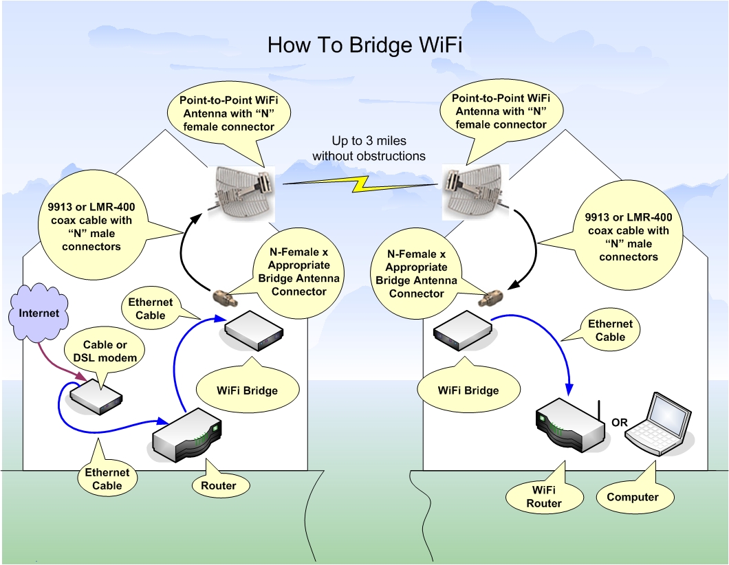
A WiFi Bridge can link your network to
another network so that resources like Internet
can be shared. Bridging devices work together in
pairs so you will need two units. One unit is
placed at each network. When a WiFi connection is
established between both bridging units then the
two networks become one.
A WiFi bridge is different from a WiFi
router because it is able to connect two networks
using WiFi. A normal WiFi router must connect to
other networks using an Ethernet cable.
Setup
It is best to initially setup both bridging units
in the same room before relocating them to their
final location. Run the setup CD on a nearby
computer and follow the instructions. Once both
bridges are communicating with each other then you
can continue by placing each item in its final
location.
Most WiFi bridging devices come
pre-installed with a small antenna that can be
upgraded to a larger antenna for extended long
range WiFi. When using a bridge it is best to
mount your antenna outdoors where line of sight
can be achieved without obstructions. In this case
you may need to extend low-loss coaxial cable
between the antenna jack on the bridge and the
outdoor antenna.
Boosting Power
If all your equipment is setup and aligned
properly and you are still not getting connected
then you may need to boost the power. This
requires another piece of equipment called a WiFi
Signal Booster. This WiFi
Signal Booster
has two coaxial connectors so it can be placed
in-line with the antenna. Connect the "Input" jack
on the signal booster to the antenna jack on the
bridge. Next connect the "Antenna" jack on the
signal booster to the coaxial cable that leads to
your outdoor antenna. If you're using the linked
signal booster above
with the equipment used in this illustration,
then you will also need a special
connector fitting
along with a special
pigtail.
For even more power add a WiFi signal booster
to both bridges.
FCC Power Output Rules
Unfortunately there are power restrictions (laws) when
using WiFi that if exceeded could land you in
jail. The FCC limits your total power output using
a sliding scale. The scale starts at 30dBm of
amplification power while using a 6dBi directional
antenna. Then for every 1dBm you drop in
amplification power you can increase the power of
your directional antenna by 3dBi.
Using a larger point-to-point antenna, your beam
pattern will cover less area and cause less
interference for others. This is why the FCC
allows this sliding scale.